


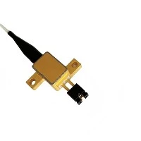
Dot, line, and cross laser modules are compact, high‑stability semiconductor laser assemblies widely used in industrial positioning, alignment, measurement, and machine vision. This paper systematically analyzes their optical principles, structural composition, performance parameters, application differentiation, selection criteria, and operational maintenance, providing a technical reference for engineering integration and application optimization.

1. Introduction
Semiconductor laser modules have become standard auxiliary components in modern industrial equipment due to their small size, low power consumption, high brightness, and easy integration. According to the output beam morphology, they are mainly divided into three categories: dot laser modules, line laser modules, and cross laser modules. These modules provide real‑time, intuitive optical reference lines, significantly improving alignment accuracy, operational efficiency, and processing consistency.
2. Structural Composition and Working Principle
Industrial laser modules share a similar core structure, consisting of a laser diode (LD), drive circuit, optical assembly, and mechanical housing. The difference lies in the optical design used to shape the output beam.
2.1 Laser Diode and Drive Circuit
Most industrial modules use visible laser diodes, typically at wavelengths of 635 nm / 650 nm (red), 532 nm (green), and 450 nm (blue). Infrared wavelengths such as 808 nm and 980 nm are used for non‑visible sensing and detection.To ensure stability under temperature fluctuations, industrial‑grade drives adopt:
ACC (Automatic Current Control) for constant current output
APC (Automatic Power Control) for constant optical power, effectively suppressing power drift caused by temperature changes.
2.2 Optical Shaping Mechanism
Dot Laser ModuleUses a precision focusing lens to compress the divergence angle and output a small, concentrated light spot. It features minimal beam divergence and high positioning accuracy.
Line Laser ModuleUses a cylindrical lens or DOE (Diffractive Optical Element) to expand the point source into a one‑dimensional fan‑shaped line beam. The line uniformity, length, and thickness depend on the optical design and fan angle.
Cross Laser ModuleGenerates two mutually perpendicular line beams through orthogonal cylindrical lenses or cross‑type DOE. It provides dual‑axis reference with strict right‑angle accuracy.

3. Performance Characteristics and Typical Applications
3.1 Dot Laser Module
Features: Small spot size, low divergence, high precision, low power consumption.
Typical parameters: Power 5–50 mW, spot diameter < 1 mm, divergence angle < 1 mrad.
Applications: Tool setting, target positioning, punching alignment, automation grasping.
3.2 Line Laser Module
Features: Continuous linear reference, adjustable length and fan angle, uniform line distribution.
Typical parameters: Power 10–100 mW, fan angle 10°–110°, line length 0.5–10 m.
Applications: Cutting and scribing, straightness detection, 3D profile scanning, assembly positioning.
3.3 Cross Laser Module
Features: Simultaneous X‑ and Y‑axis datum, high vertical accuracy (< 0.1°).
Typical parameters: Power 5–50 mW, uniform line width, stable right‑angle output.
Applications: PCB mounting, welding alignment, equipment calibration, installation and leveling.
4. Key Selection Criteria
Wavelength and Power Red lasers are cost‑effective; green lasers have higher visibility under strong sunlight. Indoor positioning usually uses < 5 mW; outdoor or long‑distance applications require higher power.
Beam Quality Dot modules require small divergence; line and cross modules require uniform intensity, straight lines, and minimal distortion.
Stability and Environment Resistance Industrial applications demand APC drive, operating temperature range of −10 °C to 50 °C, and protection level up to IP65 or IP67.
Electrical Interface and Control Common supply voltages are 5 V, 12 V, 24 V DC. TTL modulation supports external switching and synchronization with PLC or vision systems.
Mechanical Integration Focusing mode (fixed or adjustable), mounting structure, heat dissipation design, and anti‑vibration capability must match the equipment.

5. Installation, Maintenance and Safety
5.1 Installation and Maintenance
Secure mounting to avoid vibration displacement.
Keep the optical window clean using lint‑free cloth and isopropyl alcohol.
Avoid high‑temperature and high‑humidity environments.
Do not hot‑plug power supplies to prevent LD damage.
5.2 Common Faults
Dim or unstable output: LD aging, dirty lenses, or poor heat dissipation.
Non‑uniform lines: misalignment of lenses or DOE.
Severe temperature drift: lack of APC or abnormal drive circuit.
5.3 Laser Safety
Products comply with IEC 60825:
Class 2: < 5 mW, safe for short‑term visual exposure.
Class 3R / 3B: 5–500 mW, direct viewing and specular reflection are prohibited.Protective signs and safety barriers are required in industrial environments.
6. Conclusion
Dot, line, and cross laser modules are highly versatile optical positioning components with distinct optical characteristics and application scenarios. Scientific selection based on working distance, environmental conditions, accuracy requirements, and control interfaces can significantly improve equipment stability and production efficiency. With the development of intelligent manufacturing, high‑uniformity, miniaturized, and digitally controlled laser modules will become mainstream trends, further expanding their applications in automation, machine vision, and precision processing.
Contact information:
If you have any ideas, feel free to talk to us. No matter where our customers are and what our requirements are, we will follow our goal to provide our customers with high quality, low prices, and the best service.
 Email:info@loshield.com; laser@loshield.com
 Tel:0086-18092277517; 0086-17392801246
 Fax: 86-29-81323155
 Wechat:0086-18092277517; 0086-17392801246


