Fiber-coupled laser diodes are the backbone of modern photonic systems - from 1310 nm telecom transceivers to 976 nm pump lasers for fiber amplifiers and 1550 nm LiDAR sources.
Selecting the correct interface involves two independent but equally critical domains:
Optical interface – the fiber connector that determines coupling efficiency, insertion loss, and back-reflection tolerance.
Electrical interface / package – the mechanical housing and pinout that define thermal management, high-frequency signal integrity, and board-level assembly.
Mismatching either domain leads to costly rework, damaged fibers, or degraded laser lifetime.
1. Optical Interfaces – Fiber Connectors
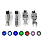
The connector at the end of the pigtail fiber dictates how light enters the external optical system. Four families dominate the market.
1.1 FC Series (Ferrule Connector)
The FC connector uses a threaded barrel for secure, vibration‑resistant mating.
FC/PC (Physical Contact) – flat or slightly radiused polish. Return loss ≈ 40 dB. Suitable for low‑speed systems (≤1 Gbps) where moderate back‑reflection is tolerable.
FC/APC (Angled Physical Contact) – 8° angled polish. Return loss > 60 dB (often 65 dB). Mandatory for analog video transmission, coherent detection, precision metrology, and any laser diode sensitive to external feedback (e.g., 405 nm, 520 nm, 638 nm visible diodes). The 8° angle directs reflected light into the cladding.
Design note: FC/APC and FC/PC are not interchangeable. Mixing them damages both ferrule end‑faces.
1.2 SC and LC – Modern Communication Standards
Both use a ceramic ferrule (2.5 mm for SC, 1.25 mm for LC) and a push‑pull latch mechanism.
SC (Subscriber Connector) – robust, low‑cost, and widely used in GPON, Ethernet, and industrial control. Typical insertion loss <0.25 dB.
LC (Lucent Connector) – half the footprint of SC. Preferred for high‑density faceplates (e.g., 48 ports in 1U) and all small‑form‑factor pluggable transceivers (SFP, SFP+, QSFP).
Both are available in PC and APC polishes, though LC/APC is less common due to space constraints inside transceivers.
1.3 SMA – High‑Power Transmission
The SMA connector abandons the ceramic ferrule entirely. Instead, a metal threaded sleeve directly grips the fiber's stainless‑steel jacket.
Key advantage: withstands high temperatures (>150 °C) and continuous optical powers >5 W without ferrule damage.
Typical applications: medical lasers (urology, dermatology), high‑power industrial cutting (1 µm – 2 µm), and pump laser delivery.
Disadvantage: higher insertion loss (≈0.5 dB) and poorer return loss (≈20 dB) compared to FC/APC.
1.4 Bare Fiber & Custom Interfaces
In R&D or ultra‑high‑power systems (>10 W), connectors are often omitted entirely. The fiber is either:
Directly fusion‑spliced to the system fiber (lowest loss, permanent),
Terminated with a custom metal capillary for mechanical clamping, or
Left as a bare cleaved end for free‑space coupling through lenses.
Custom interfaces also include PM (polarization‑maintaining) connectors (e.g., FC/APC with a key aligned to the slow axis) used in coherent communications and interferometric sensors.
2. Electrical Interfaces – Packages & Pinouts
The package determines how the laser diode is powered, cooled, and mechanically mounted. Three architectures cover >95 % of commercial fiber‑coupled diodes.
2.1 Butterfly Package – High‑End Standard
The 14‑pin butterfly (hermetic, dimensions: 20.8 mm × 12.7 mm) is the workhorse of precision photonics. It integrates:
TEC (thermoelectric cooler) – stabilises the laser temperature to ±0.01 °C, critical for wavelength stability (e.g., 0.08 nm/°C for DFB lasers).
MPD (monitor photodiode) – back‑facet monitor for automatic power control (APC) loops.
Thermistor (typically 10 kΩ at 25 °C) – temperature readout for the TEC controller.
Optional optical isolator – housed inside the package to block back‑reflections.
Pinout must be strictly followed (TEC+/– typically pins 1/2, LD+/– pins 7/8, thermistor pins 3/4). Used in coherent communications, tunable external‑cavity lasers, and precision metrology.
Variant: Mini‑butterfly (14‑pin, 12.7 mm × 7.6 mm) for space‑constrained modules.
2.2 Coaxial / TO‑CAN Package – Cost‑Effective
The transistor‑outline (TO) package resembles a metal‑can transistor. Common sizes: TO‑46 (4.6 mm diameter) and TO‑56 (5.6 mm diameter).
Standard TO‑CAN – up to 3 pins (LD+, LD‑, case ground). No TEC. Simple, low cost, and widely used inside SFP/SFP+ transceivers or consumer LiDAR.
TO‑CAN with RF connector (IEC 62148‑12) – adds a coaxial RF input (e.g., SMA or GPO) for high‑frequency modulation >10 GHz, bypassing the inductive TO header.
Limitation: Without active cooling, wavelength drifts with ambient temperature. Suitable for uncooled applications where a ±1 nm drift is acceptable.
2.3 DIL (Dual In‑Line)
A simplified, non‑hermetic predecessor of the butterfly. Available in 8‑pin, 14‑pin, or 22‑pin variants. Lacks integrated TEC in most versions; used for low‑power (<100 mW), uncooled applications where cost is paramount.
3. Practical Mapping – Package + Connector Combinations
The table below summarises the most common industry pairings.
| Application Example | Typical Package | Optical Connector | Key Consideration |
|---|---|---|---|
| Precision metrology (coherent sensing) | 14‑pin butterfly | FC/APC (often PM fiber) | Return loss >60 dB |
| Tunable laser (100 kHz linewidth) | Mini‑butterfly | FC/APC + isolator | Thermal stability |
| SFP/SFP+ transceiver (internal) | TO‑46 / TO‑56 | LC receptacle or pigtail | Compact footprint |
| 10 W industrial cutting laser | Custom copper block | SMA or bare fiber | High power handling |
| Low‑cost data‑com (1 Gbps) | Coaxial TO‑can | SC (PC polish) | Cost <$10 per diode |
Quick decision guide:
Cooling needed? → Yes: butterfly package; No: TO‑CAN (if power <100 mW) or DIL.
Reflection sensitive? → Yes: FC/APC polish; No: FC/PC, SC/PC, or LC/PC.
High‑density board design? → LC connector + mini‑butterfly.
High power (>1 W continuous)? → SMA or bare fiber (avoid FC/APC, which has glue‑based ferrules).
4. Summary & Future Trends
No universal interface – the correct choice balances thermal, optical, cost, and board‑level constraints.
Current trends:
Miniaturisation – mini‑butterfly and nano‑packages for co‑packaged optics (CPO) and on‑board optics.
Passive cooling improvements – pushing TO‑CAN packages to 1 W continuous without TEC.
Higher fibre power handling – new connector materials (e.g., glass‑ferrule with metal‑free bonding) that tolerate >20 W without glue degradation.
Integrated monitoring – MPD and isolator increasingly integrated into TO‑CAN packages, blurring the line between low‑cost and high‑end.
Pro tip for prototyping: Start with a 14‑pin butterfly + FC/APC assembly. It offers maximum flexibility (TEC, monitor, isolator option) and the best optical performance. For volume production, down‑select to TO‑CAN + LC receptacle once thermal requirements are verified.
Contact information:
If you have any ideas, feel free to talk to us. No matter where our customers are and what our requirements are, we will follow our goal to provide our customers with high quality, low prices, and the best service.
 Email:info@loshield.com; laser@loshield.com
 Tel:0086-18092277517; 0086-17392801246
![]() Fax: 86-29-81323155
Fax: 86-29-81323155
 Wechat:0086-18092277517; 0086-17392801246


